Controlling the Flow: How low can you go?

Managing flood risk is one of the most important tasks facing designers today, and one that requires significant expertise to guarantee success. Luckily, the precision engineering of flow control has an ever-growing variety of technologies and techniques that help to prevent flooding.
Sustainable design is prioritised when aiming to prevent, control or contain flooding. The designer’s primary objective is to make the drainage solution behave in a similar way to the pre-development, natural environment. Typically, this is achieved by controlling the peak rate of discharge and introducing flow attenuation.
Designers are now being asked to achieve lower and lower flow rates by using constraints such as greenfield runoff rates. These design approaches often produce flow rates below 2 l/s, sometimes much lower.
The most frequently asked questions in relation to the design of flow control systems relate to the so-called ‘limbo question.’
'What is the minimum flow rate to which you can control?’
or
‘What is the minimum acceptable opening size for a flow control?’
How practical are very low flow rates?
The only limiting factor on the minimum flow rate a Hydro-Brake® flow control can manage is the physical manufacturing process and what is deemed feasible or appropriate to make and install.
The problem with very small flow controls is the increased risk of blockage, so whilst these flow controls are possible to make, they are not necessarily suitable in a drainage network.
Therefore, the minimum size of a flow control is often driven by industry guidance.
What does national guidance say?
There are now a variety of industry guidance documents applied at national and regional levels and they are not always consistent in terms of their stance on minimum flow rates or minimum flow control sizes.
Some of these are highlighted in the table shown here.
Organisation / Document | Minimum Flow Control Size / Minimum Flow rate |
Sewers for Adoption 7th Edition | 100 mm |
Design and Construction Guidance , (Sewerage Sector Guidance, Appendix C)
| >50 mm for protected static controls and >100 mm for unprotected static controls. |
The SuDS Manual (C753) | 75 mm or 100 mm if to be adopted by a sewer undertaker. ‘Significantly smaller’ if private / adopted by other organization, if appropriate and agreed. |
BS8582:2013 | As agreed with future owner (minimum flow threshold could be 5 l/s or lower) (controls <25 mm are possible if protected) |
EA SCO30219 | 5 l/s |
There are issues with the guidance, particularly when it comes to low flow rates vs larger orifices. Many guidance documents now stipulate that orifices must be at least 100 mm in diameter, which is a trend upwards.
A 100 mm orifice is simply not possible when discharging at 2 l/s, which is what designers are being asked to achieve, so there are conflicting requirements.
It is clear to see why designers are not sure what to do...
What is the solution?
There needs to be an open discussion between designers, local authorities and water companies to find a practical solution.
All parties should adopt a risk-based approach: what is the risk of flooding downstream vs the risk of blockage? Is the risk of blockage greater than the risk of downstream flooding? If so, go for higher flow rates and larger openings; if not, go for lower flow rates and smaller openings.
It is imperative to use flow controls that offer the largest orifice size possible.
For this reason, it is imperative to use flow controls that offer the largest orifice size possible. The Hydro-Brake® Optimum has larger orifice sizes compared to other flow controls.
It can be also be customised so that the orifice size is as large as possible to mitigate the risk of blockage whilst still meeting the requested discharge rate.
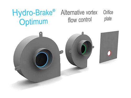
A more efficient control like the Hydro-Brake® Optimum will start to throttle the flow at a later stage, by which time a lot more water has been released off site – this difference in performance reduces the storage or attenuation volume required.
This is important as constructing underground storage is expensive and above-ground storage can take up land which could be used for development. Any site with a Hydro-Brake® Optimum flow control needs up to 15% less storage than if an alternative vortex control is used.
Don’t forget that the flow control is a very small part of the overall cost for the attenuation system, so it is a false economy to select a cheaper flow control if you then find you need substantially more storage.
Constructing underground storage is expensive and above-ground storage can take up land which could be used for development.
How to protect your low flow control
Low flow rates are achievable with a 50 mm orifice, but designers must make sure that any resulting orifice sizes less than 100 mm are protected. Key things to consider are:
- Treatment – Remove any gross pollutants or large objects that could cause blockage before they reach the flow control using a system such as a Downstream Defender® vortex separator.
- Screening – Protect the flow control inlet from debris with a mesh screen. This is supplied as standard for all our Hydro-Brake® Optimums below 50 mm.
- Monitoring – Receive instant alerts if there is a blockage with systems such as Hydro-Logic® Smart Monitoring.
Changing weather patterns are making it more important than ever to precision engineer flow control and attenuation to mitigate flood risk. A range of flow control devices are available to achieve optimum performance, from the smallest to the largest schemes. Particular care must be taken to select the right device and avoid compromising the project by switching out to an inferior product.
Designers can use a range of support to optimise their designs, including online software tools and manufacturers’ technical expertise. Our online design tool is a product selection and sizing tool that gives you the flexibility to compare flow control design options, output detailed design drawings and hydraulic data, and import the results into commercially-available hydraulic modelling software.
Learn more
Find out more by visiting the Hydro-Brake® Flow Control series page or by downloading the ‘Going with the Flow’ white paper.